555-Timer Oscillator for Ultra Low-Power Devices
Using the Astable Multivibrator circuit with a CMOS 555 Timer, power consumption on battery-powered sensors can be drastically reduced to microamps. This guide demonstrates two common circuits that can be used to achieve this.
Since I've begun working on some remote, battery-powered devices, I have been looking for ways to lower power consumption. I experimented with some methods like using sleep functionality of microcontrollers, trying to limit losses in voltage conversion, etc. As I went through lots of these power consumption optimizations, I found that often they did not have really significant impact.
Using the Astable Multivibrator circuit with a CMOS 555 Timer, power consumption on battery-powered sensors can be drastically reduced to microamps while not in use. This can be a great fit for use-cases like remote sensors that only need to turn on once in a while.
Why CMOS? A regular 555 timer IC will have significantly more power consumption than a CMOS 555 timer, though they are functionally equivalent. We will dive deeper into CMOS components in another, but suffice it to say that an equivalent CMOS part will usually feature significantly lower power consumption.
555 Timer OscillatorThis guide demonstrates how a 555 timer can be used to drastically reduce power consumption in low-power Arduino projects by creating an oscillating power switch where the on and off times are configurable. Using this method, even systems that are not particularly efficient can be made to consume fractions of a milliamp when idle!
Reducing Power Consumption in Battery Powered Devices
For battery powered projects where you're looking to extend the longevity of the device, this type of circuit can be a game-changer. I used this for a solar-powered weather station I keep outside of my home:
Low Power Solar Weather StationIn the example of my solar powered weather station (which can be seen below), I was still powering the following components 24/7:
- Arduino Nano
- 5v Boost Converter
- 5v-3.3V linear regulator
- 2.4 ghz transceiver
- DHT11 sensor
- BMP280 sensor
This project (which I have not yet posted about) is powered by a 12V solar panel array (2s 6V panels) that charge a 4.7V Li-ion 18650 battery. Prior to implementing the 555 timer switch, the sensor would last about 3-5 days before running out of battery power. After adding the switch, the device has not lost power in several months (through winter and spring) and I have never seen the battery voltage dip below 3.7V.
Battery Before CMOS 555 Timer: 3-5 days
Battery After CMOS 555 Timer: 3-5 weeks!
Let's dive into how this circuit can actually conserve power in our devices and then finish by revisiting the solar weather station use-case.
CMOS 555 Timer vs ATTiny as an Oscillating Power Switch
Before jumping into the 555 timer solution, I want to give a shout-out to the fact that this is certainly not the only and not even the best solution for this type of use-case. In this thread on Reddit, a couple users chimed in with the suggestion of using an Attiny85 rather than a 555 timer. If done right, there are a few advantages:
- Less components, can control the oscillating by programming the MCU
- Easier to add additional features like different methods of timing, shutoff based on pin input, etc.
I preferred not to go this route as I wanted to do it with a 555 timer and I preferred to control the timing by selecting resistors/capacitors rather than needing to program a microcontroller.
CMOS 555 Timer Astable Multivibrator
The main resource I used in creating this circuit was a tutorial from Electronics Tutorials. This is a great write-up that really helped me finally grasp how a 555 timer works, particularly the astable multivibrator.
Simple Circuit - Dependent Charge/DischargeThe first part of the article demonstrates a simplified version of the circuit, where the charge and discharge time are related to each other. As you can see in the formula below, the HIGH time is designated by the value of R1 + R2 * .693 * capacitance of the capacitor, while the LOW time is dependent only on R2. With this circuit it is not possible to have an HIGH time less than the LOW time.

Using this circuit, you'd need to either use a P-channel MOSFET or transistor OR invert the signal if using an n-type.
Improved Astable Multivibrator CircuitIn the above "improved" circuit, 2 diodes are used to isolate the charge and discharge paths, which allow the HIGH and LOW durations to be controlled independently via the respective resistances of R1 and R2.
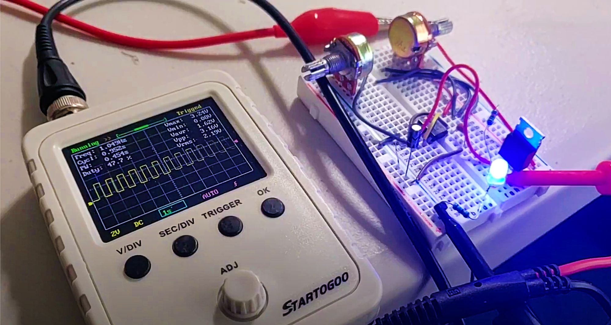
Here is an example of the first version (without the extra two diodes) wired up to a breadboard with two potentiometers to control the timing, switching a P-channel MOSFET:
Astable MultivibratorNotice the HIGH/LOW pulses shown on the oscilloscope above.
Soldered to strip boardOnce I was happy with the circuit, I soldered it to strip-board. This type of prototyping board is nice to work with as it is really easy to cut/sand down to a smaller shape and rather inexpensive. Just be sure to do it with proper masks/ventilation as sanding/cutting fiberglass is not good if there is any inhalation going on.
Assembled 555 Timer Oscillating SwitchHere is the finished prototype. It was consuming about 100 microamps in the OFF state. In the end I opted to use an IRF510N N-channel MOSFET as the switch.
Real World Application - Powering a Li-ion Powered Solar Weather Station
As promised, we now return to the actual use-case. I installed the oscillating switch in my solar-powered weather station. The solar charger, a simple MPPT controller based on the SD30CRMA IC, still charges the battery even when the switch is in the OFF state, but it powers on the weather station for 10 seconds every 2 minutes.
Assembled in Solar Weather StationBy adding in the oscillating switch, the device doesn't really come close to running out of juice. I know there are ways to further optimize this timing circuit to consume much less than 100 microamps, but for my purposes it was a great improvement.
I also designed a couple PCBs with this circuit so I could have an adjustable part that I could use in other circuits. In another post I'll go over the design process for that.
As always, please get in touch on twitter with any questions, suggestions, comments, whatever!