Turning a $10 kitchen scale into a WiFi smart scale for Home Assistant
Over the years I've seen a few posts on Reddit demonstrating the use of a load cell with an internet-connected microcontroller as a weight-based filament sensor for 3D printing. I decided to embark upon a similar project, retrofitting a $10 kitchen scale.
It can be really fun to take an inexpensive product and, with a little bit of DIY magic, enhance its functionality. It's a sense of satisfaction a bit different from that of building something end to end from scratch, but every bit as good.

I hopped on Amazon and found an Amazon Basics kitchen scale which at time of purchase was about $10 shipped. The entire scale was actually cheaper than some listings for the same type of discreet 20kg-rated load cell found inside, plus we get a factory made case, scale platform, buttons, etc.
What is a load cell?
A load cell is a device that converts some type of force into an electrical signal that can then be reliably read and used for some purpose. Let's take a look inside the kitchen scale to get a better idea of how it works:

Looking at the above photo, let's take stock of the internals and what they do:
- To the left, out of focus, is the battery pack, where 2x AAA batteries supply power to the device, supplying power to the green circuit board on the right.
- To the right, the metal bar with 4 threaded screw holes in a single-file line, is the load cell.
- The bundle of 4 wires connects the load cell to the circuit board. In the above photo, the LCD screen has been removed, and we can see the incoming wires from the buttons (top and bottom), battery (top left), and load cell (center left).

The load cell in this kitchen scale, a cantilever load cell like the one depicted in the diagram above, operates on a pretty simple principle. One end of the load cell is affixed strongly to a base, while the opposite end is strained (in the case of a scale, there is a platform strongly affixed to the opposite end).
Though we won't go into the how it in this post (I highly recommend this GreatScott video on the topic), the strain placed on the load cell by the force pushing down by the load is then translated into a very tiny voltage. Actually, this voltage is so small, in the microvolts range, that it is pretty much useless to us as is.
The voltage generated by the strain placed on the load cell, being so small, must be amplified, and some post processing must be done to eliminate noise from the results. Most microcontrollers actually aren't capable of doing this out of the box, and that is certainly true of the ESP32 which I'm using for this project. The circuit board that came inside this kitchen scale was, of course, designed specifically for this purpose, so it includes an IC that handles the load-cell reading, processing, and scale functions all in one. We need more than a simple scale reading on an LCD screen, we'll just de-solder and remove the included green PCB.
Adding WiFi to the kitchen scale
Now that we understand how this thing works, it's time to make it even smarter. While we won't be using the original PCB or the original battery pack (I'll just be powering the scale via the ESP32's micro USB port since it will be on for long periods of time), we can still use every thing else.
What do we need for the retrofit?
- ESP32 or similar microcontroller with WiFi connectivity - for our purposes we'll be writing the code in C++ with the Arduino IDE.
- HX711 load cell amplifier - this module is going to allow us to get a stable, accurate reading from the load cell.
- SSD1306 i2c OLED screen (128x32)
Smart scale schematic

The schematic above details all the soldering connections we'll need to make in this smart scale build.
Let's start out by soldering the load cell to the HX711 module, which we'll then attach to the ESP32 board:

Depending on which microcontroller you use, the physical arrangement might be different. I just made a best effort attempt to fit everything snugly inside of the scale enclosure, and this is what I ended up with.
Next, connect the HX711 VCC, GND, data, and clock pins to the ESP32 followed by the OLED screen connections and the two buttons:

With all the connections soldered and tested by flashing the microcontroller via USB, we can start to program the smart scale!
Writing Arduino code for a smart kitchen scale
We'll be writing our scale's firmware in C++ using the Arduino IDE. For our purposes, we'll install a few external libraries to make our lives a bit easier.
Grab the following libraries before we get started:
- HX711 by bogde
- Adafruit_SSD1306 by Adafruit
- ezButton by ArduinoGetStarted
- We'll assume that you have the EEPROM, WiFi, and WebServer libraries that are a part of the ESP32 core.
Start by importing all the libraries we'll need:
Then we'll initialize all of our settings and objects we'll use in our program. If you used a different microcontroller or different pin layout, you'll need to adjust them accordingly in the firmware:
In the above code, we initialize the components of our smart scale:
- Internet connection/web server
- OLED screen
- Load cell amplifier
- 2-button interface
Hop on over to the Github repository to check out the rest of the firmware code. There are two values that we need to persist between device resets, and those are the device calibration value and the offset (tare) value.
The calibration value is the modifier that allows you to convert the reading from your specific load cell into grams. Here is some more info about how the actual calculation works from the HX711 library readme. The offset value is the previously set tare value, which we persist so the scale readings remain consistent even when power is lost.
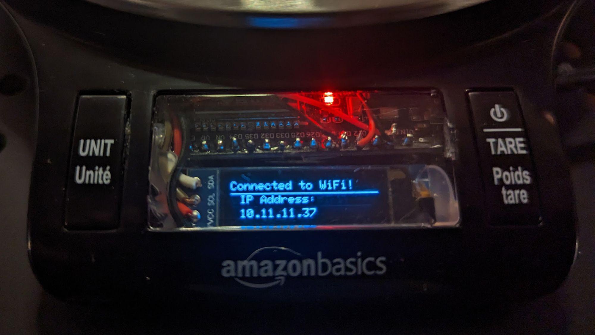
After getting set up with your own values, load up the firmware on the ESP32. If the device successfully connects to your network, you should see the assigned IP address displayed on the screen briefly. Take note of the IP so we can test out the web server endpoint in a bit.
Device calibration
I wrote up a little calibration UI that uses the existing buttons. Here's how it works:

- Press the left (UNIT) and right (TARE) buttons at the same time to enter calibration mode
- Place an item of a known weight onto the scale
- Use the left(-)/right(+) buttons to set the calibration value. Double pressing a button will move the number by 10.
- When the correct value in grams is displayed, press the two buttons at the same time once again to set the calibration value.
- Remove the item from the scale and press tare to zero out the scale, if necessary.
Reading the scale over the network
Now that our newly-smart scale is running the custom firmware and powered on and calibrated, we can test out its new capabilities!
Open up a browser on a device connected to the same network as the scale and navigate to http://{scale IP}/read_scale in a web browser and you should get a JSON response with the current scale reading in grams.
From here on out, the possibilities are endless. Here are some ways you could use your connected smart kitchen scale:
- Keep Octoprint updated about remaining 3D print filament in real time
- Connect it to Home Assistant and use it in the kitchen to know when you need to buy some more of coffee, sugar, salt, peanut butter, etc.