Homemade Battery-Powered Alexa Smart Speaker
Using a disassembled Echo Flex device, I made a portable, wireless smart speaker with an integrated phone charger. Aside from being a fun project, it is cool to have a powerful speaker that just integrates with the rest of my Alexa devices.
Intro
I made a DIY battery-powered Alexa device. Many hobbyists are weary of using Amazon or Google smart speakers at home - I'll write up a post about those concerns another time. For now, I'll just say that I value the convenience of being able to easily get multi-room music setup that just works with my streaming services and home automation.
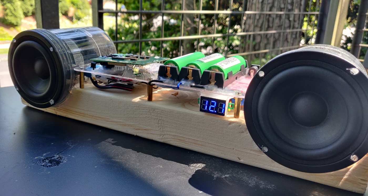
I eventually ended up with this:
The finished productA few months back I saw the Echo Flex on sale for $9.99, and decided to order a few. Since I had a couple of these Echo Flex devices sitting around, I figured I should do something with it. Eventually I took it out of the packing, plugged it in, and noticed that it is a nice little device - but its integrated speaker is horrible and not much use. Looking at it though, it had a lot going for it for a device that cost $9.99 (admittedly as a promotion): WiFi, bluetooth, voice activated, audio output, usb phone charger.
I decided to go ahead and disassemble it to see if I could easily create this custom speaker. Read on for a guide on how this project went. First, a list of the parts and tools used:
Parts List
Power Supply
- MP1584EN DC-DC Buck Converter
- CC Buck Convertor for charger
- Self-lock power switch
- 3S Li-ion protection PCB with balancing
- 1N5822 Schottky Diode from this set
- DC barrel power jack
Audio/Speakers
- PAM8403 Stereo 3W Amplifier PCB
- 2x 3" 4Ohm 15 watt Speakers
- 1000 Microfarad capacitor from this set
- 3.5mm male audio connector
- 2x Audio transformers
- Ferrite beads
- 220 picofarad ceramic capacitors from this kit
- 2-pin screw terminals for speaker out
- 16-AWG speaker wire
Tools/Materials
- Soldering iron, lead-free solder, fume extractor, flux
- Crenova Multimeter
- Irwin wire stripping tool
- Polycarbonate sheet
- 20mm standoffs
- Aviation snips
- Metal hole punch
- 1.3 amp rotary tool
The Build
This was one of those projects where everything kind of just fell into place. When I looked up "disassemble echo flex" in Google, I found a nice teardown guide by Brian Dorey, so I was able to see before ruining the device that it had what I needed.
Disassembling the Echo Flex
Stary by peeling off the back sticker with the voltage ratings. This will expose a torx screw. After unscrewing this, you can get to prying apart the two halves.
With back sticker peeled offIn order to pry this open, you need some kind of wedge that is decently sharp and strong. An X-ACTO knife will not really do, since it would break from the pressure. I was able to pry it open using a pocket knife and a watch case opener.
Two halves popped openBe careful after prying apart the halves not to pull on the ribbon cable connecting the two boards. You can remove the ribbon cable by opening up the latch on the side of the smaller board. Push it away from the board (closer to the cable) to release.
Now you can remove the rest of the internal chassis screws and remove the boards.
Here you can see the AC-DC converter still attached (we don't need it for this project) and the power module.
AC-DC convertor and power moduleHere is the main board, which contains the wireless radios and audio circuitry. There is a small speaker (back, above the two boards) which is connected via spring clips to the main board when assembled:
Main board, DAC, and power moduleAfter disassembling, power up the board directly with 5V just to make sure it all still works:
Powering up the Flex directly with 5V DCStructure
Now that the brains of the smart speaker were good to go, let's focus on getting the body together. Start by using aviation snips and a metal hole punch to shape this polycarbonate sheet into a panel to hold the circuitry. Using 20mm standoffs, there will be room for components on both sides of the panel:
Polycarbonate panel cut to hold the circuitryAfter getting the panel measured and ready, glue on 18650 battery holders (these type are the absolute best kind that I have found, but are very expensive on Amazon. If you have time, order them on AliExpress, where they can be found for under $1 each). Then, add a barrel power jack for charging.
18650 battery holders and barrel jack added to panelNow onto the wooden block that will hold everything together. Cut this to size to have enough room to hold the panel and the two speakers on either side. I had some empty ice-cream containers that I decided to use to house the speakers, as they were a perfect fit.
Cut out slots for speakers and standoffs to hold panelWithout many power tools I used an old-fashioned hand saw, but you might have something less rudimentary. Cut out slots and knock out the pieces with a hammer. Using a rotary tool (like this 1.3 amp rotary tool) you can sand out the slots and cut pilot holes to screw in the standoffs.
Power circuitry and main board
Next, set a CC Buck Convertor for charger to output 12.6 volts and maximum 600 mA for the 3S Li-ion battery. Notice in the photo that we're setting it both with load applied and with the diode in place, to account for the voltage drop.
Set charging voltage/CC level on buck convertorAfter setting and testing the charging module, glue all the power components to the underside of the panel. Take care to arrange them keeping in mind how the BMS board and power components are wired to each other, in order to limit the length of the connecting wires.
Glued charger, BMS, and supply voltage buck convertorFinally, you can solder the connections together with wire. Use a higher-gauge wire for the connections that you expect to transfer any significant current.
Wire up power componentsAdd a power switch between the P+ terminal of the BMS and the positive input of the supply buck convertor. When adding a power switch to a battery powered circuit, be sure to place it in a location where the off-state will not be leading to unnecessary power consumption. In this case, placing it before the input of the buck convertor rather than the output ensures that the convertor will not be consuming current while the device is off.
Power switch addedAfter connecting all the power components, verify that the charging is working and the buck convertor is outputting the correct supply voltage (5V in our case). Once you verify that, connect the Echo Flex main board and power board.
Echo Flex components glued on and connectedThe power module contains a USB charger built in, so be sure to position it so it will be accessible. I glued the main-board on with the built-in speaker for testing purposes. If I was to do it again, I would have just left it out. However you position the mainboard, be sure to add heatsinks to the shields, in the same place as the residual thermal paste from the connection with the other half.
Audio
Since we are getting the audio out of the headphone jack of the Echo Flex, we will need an amplifier in our design. The PAM8403 is a great value hobbyist Class D amplifier, and is available in pre-made PCB modules usually for under $1 each, depending on where you purchase it.
PAM8403 wired to headphone outUse a 1000 microfarad capacitor across the +/- supply terminals of the amplifier PCB to ensure a stable supply. After initially wiring the headphone output to the amplifier input, test the sound with the speakers.
Testing the speakersUpon testing, I found there to be lots of interference, probably from all the activity coming from the Echo Flex board. I had some audio transformers on hand so looked around the internet for an example of how to filter interference on the PAM8403. There is lots of conflicting instructions, talking about filtering the input, output, using capacitors, transformers, ferrite beats, resistors. It can all be a bit confusing especially if you (like me) don't have a deep understanding of audio electronics.
Audio transformer schematicI settled on this design to filter the input, without the resistors, based on the discussion in this thread on GitHub. I found that it eliminated what I would estimate to be more than 90% of the interference noise. There is still some barely audible noise that can be heard if you put your ears up to the speaker. Not sure how to get rid of this.
Adding the audio transformersI looked up some more schematics and found ones involving ferrite beads and ceramic capacitors, so I tried this one:
Output filter schematicNot sure if it was supposed to be on the output of the amplifier, but that is what the schematic appeared to show from my interpretation. Unfortunately, this did not make much of a difference and that very low static noise remained. If anyone has any insight on this, please let me know and I'll update the guide.
Ferrite beads and ceramic capacitor on outputFinal Assembly
Now it's time to put it all together. Fit the panel to the wooden block in order to make sure there is proper clearance when fitting the speaker enclosures.
Fit panel to wooden blockAt this point, drill holes in the speaker enclosures that will allow you to pass through the speaker +/- wires. Aim to place the holes so they will exit on the underside of the polycarbonate panel. Have a lot of hot glue sticks ready and start glueing.
Attach speaker cases to wooden blockWait some time for glue to dry and continue to fill up the cracks with hot glue. My sanding job was very uneven so I relied on hot glue to get a good stable fit.
Glue insulation to speaker enclosuresThe final thing to do before adding in our speakers is to glue in some insulation. Use crazy glue to coat as much of the enclosure as possible in the insulation material. Once you are satisfied with the insulation layer, and the speaker can fit in, glue the edges of the speaker to the lip of the enclosure.
The finished productAnd there we are. This was a really fun project and it has been nice to add a battery powered Alexa speaker to my multi-room music setup. I used 3 Li-ion 18650 batteries with ~3500 mAh capacity each, resulting in about 6-8 hours of playing time. I haven't scientifically tested the battery life, but so far seems to be pretty good. If I was planning to use this for extended trips or time outdoor, I would probably add some more cells to the battery.
Please note that I only link products that I have bought and tested myself, and some of the links above are Amazon affiliate links, which I earn a commission from (at no additional cost to the buyer).