DIY Gigabit Passive PoE Splitter - Sharing data signal and power on the same wires
I build a homemade PoE splitter that supports Gigabit connectivity. It's a little more complex than the more simple PoE splitter that uses only spare wire pairs. Overall, it was a great opportunity to learn more about PoE.
This post is part of a series, the first of which was a guide to building a DIY Power over Ethernet passive splitter that uses the "spare pairs" to transfer power and does not allow signal transfer. This means that full gigabit connectivity is not possible, as that requires all 4 ethernet pairs to carry a signal. Here is a useful Wikipedia article about twisted pairs and the different ethernet standards.
I set out to build a gigabit-capable PoE splitter that would be a step up from the previous one. I decided to add in a PoE pulse transformer, so we could safely send data to the device on the spare pairs, and bridge rectifiers, to protect against reverse polarity on powered pairs. I'll go into more depth about these later on.
The nearly-finished productHere is the end result, prior to wrapping it in electrical tape for use. Visible on the top is the buck convertor, with a barrel jack soldered to output. Sandwiched in the middle is a board with 2 bridge rectifiers. On the bottom is the ethernet pulse transformer.
Tools/components used
- Soldering iron, lead-free solder, fume extractor, flux
- Crenova Multimeter
- MP1584EN DC-DC Buck Converter
- Spare CAT5 Ethernet cable
- Mikrotik CRS328-24P-4S+RM 24 port PoE switch
- Irwin wire stripping tool
- H6062NL pulse transformer
- 2x DB107 bridge rectifiers
- 1x 28-pin surface mount adapter cut to size (need to use something with SOP footprint and at least 24 pins) for the H6062NL. I didn't have anything on-hand with the exact footprint of the transformer
- Perf board - I used a piece from this set but you can use any type you have, as long as you can solder through-hole components to one side
The Build
Opening up the Cat5 Ethernet CableFirst thing to do is find the cable we'll use for our homemade splitter. I found a cheap-looking cable that came with some device, so decided to use that. I cut the wire where I'd have enough room to work with the device-end, since both ends need to be re-soldered to the pulse transformer.
Soldering the transformer to the adapter pcb
Let's start out by soldering the pulse transformer to the adapter board. Both of these parts are listed in the above list, and I've previously written a little guide about how to solder surface mount chips using a regular soldering iron.
Pulse transformer on SOP adapter boardWhat are ethernet pulse transformers?
Here is the H6062NL pulse transformer (see datasheet here). This component is what allows us to actually achieve gigabit speeds and power our device without damaging the device itself. This is made possible due to the electrical characteristics of AC and DC current.
There are transformers present in most ethernet circuits I've seen, and the purpose of these is to isolate the ethernet chip from dc voltage and signal noise. Transformers have the characteristic of being able to transfer AC current, but not DC current. This is what makes it possible for the signal to pass through the pulse transformer to the ethernet chip on the device, while the DC power voltage does not (which might otherwise harm the device).
What's the difference between a regular pulse transformer and a PoE pulse transformer?
There are ethernet pulse transformers that are considered PoE capable, which have higher tolerances for the expected level of power to be present on the ethernet cable, and cheaper ones that offer less protection to a device that isn't intended to be connected to a PoE cable. I got a very helpful answer to my question about the difference between PoE and non-PoE transformers on reddit.
H6062 Pulse Transformer SchematicConnecting the CAT5 cable to the PoE pulse transformer
Now it's time for us to solder the ethernet pairs to the H6062NL pulse transformer. I found figuring out this part to be a little tricky, but in the end it turned out alright.
In the above schematic, you'll notice the two sides of the part are not the same, though it might look perfectly symmetrical from the outside. According to some research (and guessing), I figured out that pins 1-12 (the T side) are supposed to connect to the chip side (or device side) and 13-24 (the M side) should connect to the cable/switch side. Note other datasheets might have other naming conventions.
Important note: one thing that I didn't do in this build is ground the unused center taps. My connection was working fine without doing so, but I understand this is supposed to be done. I am researching this and will make sure to include findings in the next iteration.
Soldering the cable end of the pulse transformerPulse transformer pin order and naming for PoE connection
Begin by soldering the cable end to the "M" side, leaving the center tap pin unsoldered between each pair. You can find out which pin is the center tap pin on the schematic as it will be labeled "CT." In the above schematic, notice every 3rd pin is labeled that way (MCT1, MCT2, MCT3, etc.). One thing to keep in mind is that you should go by the number, not the location in the schematic. Notice the pin numbers following the pattern 23,24,22 20,21,19. This can be a bit confusing, but in the photo above you can see what it looks like to solder on the pairs and leave the hole for the center tap open.
Once all the pairs are soldered, I soldered on a positive and negative lead to the center tap of the blue and brown pairs, respectively. These are the "spare pairs" where the power will be coming from. At this point, you can test whether the correct voltage is coming out of the test leads using a multimeter. You can also check the taps of the other end of the transformer to verify that the DC voltage isn't detected there.
Soldering the device end of the pulse transformerSoldering the device-side of the ethernet cable
This side should basically mirror the first side soldered. When finished soldering back the pairs, you can test with a multimeter to make sure there is no DC voltage coming through from your switch, and then test an ethernet device to make sure you are getting a data signal. I did an iperf test at each stage to validate I didn't break a connection somewhere.
Soldering the bridge rectifiers to perf boardBridge rectifiers for reverse polarity protection
Now it's time to solder on our bridge rectifiers. Here is the datasheet for the DB107. The purpose of these are to ensure that even if the DC power comes in with the reverse polarity (+ where we expected - and vice versa) or power came on the primary pairs or both pairs, we can safely transfer power on to our powered device. This video provides a pretty great explanation of how bridge rectifiers work.
You'll notice in the photo of the underside of the perf-board, the output of these rectifiers is connected in parallel.
Ethernet transformer center taps connected to rectifiersOnce we've got the bridge rectifiers connected, we can connect the leads from the center taps of the ethernet wire pairs to their inputs. Each bridge rectifier should get a + and - to both of the input terminals (which you'll notice are not themselves labeled with a +/-).
The outputs on the bridge rectifier ARE labeled with a +/- and DO have polarity. Keep this in mind and make sure not to confuse the inputs and outputs. Once you've got it all connected, you can test the output from the rectifiers and see that it matches the expected voltage from your PoE switch. You'll notice a significant voltage drop, which is caused by the diodes in the bridge rectifier. According to the datasheet, that voltage drop should be somewhere between .6 to 1.2 volts depending on the current.
Ready to connect power output to DC Buck convertorConnecting the DC-DC Buck convertor
Now that the PoE part of the device is done, and the DC voltage is isolated from the gigabit signal going to our device, we can focus on stepping down the DC voltage to a level that fits our powered device.
In the case of this particular build, I needed a 5v power source, so I used a MP1584EN DC-DC Buck Converter. I have found these to be really useful in projects, and they are reliable as long as you are careful not to break the potentiometer when adjusting output voltage.
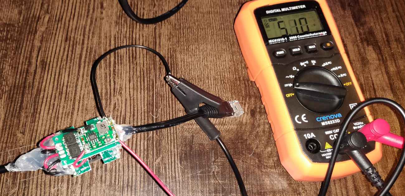
Setting the output voltage using a multimeterAdjusting the output voltage
My switch, a Mikrotik CRS328 can output what it calls "low" or "high" voltage, which is approximately 24-26 and 48-52 volts, respectively.
Since we are working with passive PoE here, keep in mind that whatever voltage you are going to be sending through the wire pair needs to be within the spec of the buck convertor you're using. The one I'm using here would not be able to step down 48 volts, so I must select the "low" setting on Mikrotik in order to use it.
If you're trying to find a good voltage to use, consider that higher voltage means higher efficiency over long distances traveling through the super thin, high-resistance ethernet wires. That comes at the tradeoff of lower efficiency since it needs to be stepped down more. If you are using this for in-rack powering of something, there isn't much to worry about in terms of voltage drop across length of the wire.
Final thoughts
Have you done a similar build or any comments? Please let me know on twitter. I am far from an expert on this stuff and just learning, so it would be great to hear some more perspectives on this.
Please note that I only link products that I have bought and tested myself, and some of the links above are Amazon affiliate links, which I earn a commission from (at no additional cost to the buyer).
Thanks!