DIY Passive PoE Splitter with Integrated DC Buck Convertor
I made a passive PoE (Power-over-Ethernet) splitter/adapter to power my Ring base station. It has an integrated convertor that is integrated into the cable.
As part of my ongoing journey to PoE-ing anything I can in my homelab (got to justify my 24 port PoE switch somehow!), I wanted to try making my own PoE splitter for my Ring base station. Previously I'd used a gigabit 802.3at PoE splitter for it, but realized I had all the parts to make my own 100mbps 5v splitter at home (the base station only has 100mbps NIC anyway).
Please keep that in mind, using this method you can't get a gigabit connection - I cover that in a separate guide to building a homemade gigabit PoE splitter, in which the 2 wire pairs we are using with the power and data signal. These passive splitters are available, but more rare and more expensive.
The total cost for the components I used in this came out to about $2 - of course this doesn't include tools and the fact that I buy sets of components, but still pretty cost effective and a nice learning experience.
Tools/components used
- Soldering iron, lead-free solder, fume extractor, flux
- Crenova Multimeter
- MP1584EN DC-DC Buck Converter
- Spare CAT6 Ethernet cable
- Male DC pigtail barrel connector from this set
- Mikrotik CRS328-24P-4S+RM 24 port PoE switch
- Irwin wire stripping tool
- MakerHawk Electronic Load Tester
The Build
Stripped off section of jacketI started out by stripping off a section of the jacket of the CAT6 cable. I used my wire stripping tool to do a shallow cut around the circumference of the jacket and then was able to slip an X-ACTO knife underneath and cut off the section.
Once you open it up, you'll see the 4 twisted pairs exposed around a plastic spine.
We are going to use two of these pairs to deliver power:
1) Blue/White pair: Positive + Power Out
2) Brown/White pair: Negative - Power Out
Make sure not to confuse the brown and orange colors - they can look pretty similar.
Cut off the end of each of these twisted pairs as close to the beginning of the opening on the side of the short end of the cable. Since it's no longer needed, you don't need to save any exposed wire on that side.
Strip all 4 wires and twist together the end of the positive pair (blue and white), followed by the negative pair (brown and white).
Now is a good time to make sure you're using the right wire pairs by connecting this to your PoE switch, enabling output and checking with the Positive and Negative wires connected to a multimeter. Take care not to short-circuit the Positive and Negative wires you have exposed.
You'll need a PoE switch that is capable of delivering active PoE power, which basically means you can set it to output power without a negotiation signal. On my Mikrotik switch, I can choose which voltage to output - you must choose a voltage under 38V, as that is the maximum rating on the input of the convertor. I am using "low" setting on Mikrotik, which is approximately 25 volts.
Buck convertor soldered onNow it's time to solder the positive and negative wires on to the + IN and - IN terminals on the buck convertor. Start by tinning the two wires using flux and solder, then applying solder to all 4 terminals on the convertor.
When solder has been applied to all terminals and both wires, you can join the +/- wires to their respective terminals on the input of the convertor with the soldering iron.
Hot Glued to the cableNow it's time to hot glue the convertor to the cable so it will be easier to work with for the rest of the project.
Soldered barrel connector to convertor outputStrip the pigtail wires and tin them, then solder the +/- wires to the +/- OUTPUT terminals on the convertor the same way the input terminals were soldered.
Setting convertor output voltage under loadNow that the convertor is connected, we need to tune the voltage of the step-down convertor. It is important to do this under load so your convertor will be properly configured to output 5V under real conditions (adding load will lead to a small voltage drop).
First, connect the cable to a PoE power source and enable 24v output. Using the load-tester with the barrel plug connected, I add enough load to be drawing around 8 watts to start. Your convertor will probably start with a voltage of around 12v if it's the same as mine. I also connected the multimeter to the +/- terminals of the load tester as the load tester does not have a high resolution voltage sensor so it isn't adequate for tuning to within .1 volts.
Very, very, carefully adjust the potentiometer pot by turning it to the right with a screwdriver. A tiny slight turn will change the voltage, so it is important to be careful and measured. I chose to go with an output voltage of around 5.07 volts at 1.5A. When no load is applied, the voltage was about 5.1 volts. This seemed to work fine for the base station.
Passive PoE settings on Mikrotik switchOn the Mikrotik switch, I chose to explicitly tell it to output the "low" voltage (~24-26 volts) and be "forced-on." Somehow it output this with the auto mode enabled, not sure how that worked but I definitely don't want it to jump to 48V by accident, so I kept all the options explicit.
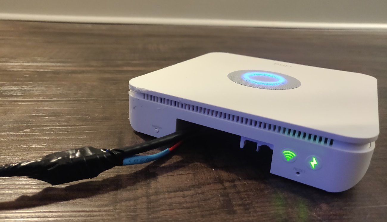
Plugged in and installed on rack shelfFinally, I taped up the convertor and cable with electrical tape and installed it on a shelf in the rack. So far so good. I am a little concerned about the heat, but with this low power consumption and 1 layer of electrical tape, it doesn't seem to heat up in any significant way.
Hope this is helpful to someone, happy to hear about any similar projects you've done!
Please note that I only link products that I have bought and tested myself, and some of the links above are Amazon affiliate links, which I earn a commission from (at no additional cost to the buyer).